
Assisted scene calibration for sports analysis

Written by:
Izan LealApril 24, 2024
In the fast-paced world of sports, every moment counts. From pinpointing a flaw in a golf swing to dissecting a crucial play in a soccer match, the ability to analyze video footage has become an indispensable tool for athletes, coaches, and enthusiasts alike. Sports video analysis goes beyond mere observation; it's a strategic approach that harnesses the power of technology to enhance performance, refine strategies, and gain a competitive edge.
This blog post will delve into the challenges and methodologies of sports video analysis, exploring how advancements in technology and innovative techniques are reshaping how we study and understand athletic performance by giving an insight into traditional and cutting-edge sports analysis methodologies.
Traditional vs new sports analysis
In the early times, sports video analysis was based on the meticulous scrutiny of recorded footage by coaches and analysts to reconstruct the movement of the players on the field. This hands-on approach required keen observational skills and a deep understanding of the sport being analyzed. Coaches meticulously reviewed each video frame, pausing and rewinding to identify players, key moments, movements, and strategic decisions, making it a very complex task that took a long time to complete.
Indeed, as technology progresses, there are now tools capable of automatically detecting players and precisely determining their positions on the field in every frame. As discussed in a previous post, player detection can be accomplished using artificial intelligence models like YOLOv5. Once a player is identified within an image, a reprojection algorithm comes into play, facilitating the conversion from camera pixel coordinates to real-world coordinates. This advancement enables a more accurate and efficient analysis of player movements and interactions within the game environment.
Camera reprojection
Camera reprojection is a fundamental technique in computer vision and photogrammetry that involves projecting 3D points onto a camera's image plane and then back-projecting them into 3D space. This process allows for tasks such as estimating camera pose or reconstructing 3D scenes from 2D images. For the sports video analysis, players' positions will be projected onto a flat field map. However, to ensure accurate reprojection, a well-calibrated camera is essential.
The camera calibration process in computer vision involves determining a camera's intrinsic and extrinsic parameters to ensure that measurements and relationships in the real world can be correctly interpreted in the image or vice versa.
The intrinsic parameters refer to the internal characteristics of a camera, which are the focal length, principal point, and lens distortion coefficients.
- Focal length (f): determines the camera's field of view and affects the scale of objects in the image.
- Principal point (c): represents the optical center of the camera's image sensor.
- Lens distortion coefficients: account for imperfections in the lens that can cause geometric distortions.
On the other hand, extrinsic parameters describe the camera's position and orientation in the 3D world relative to a reference coordinate system: the camera's translation and rotation with respect to the reference frame.
The shift from the real-world coordinate system (X,Y,Z) to the image coordinates (u,v,w) is shown in Figure 1. This shift can be inverted to map from 2D pixel coordinates to the 3D real world (Figure 2).
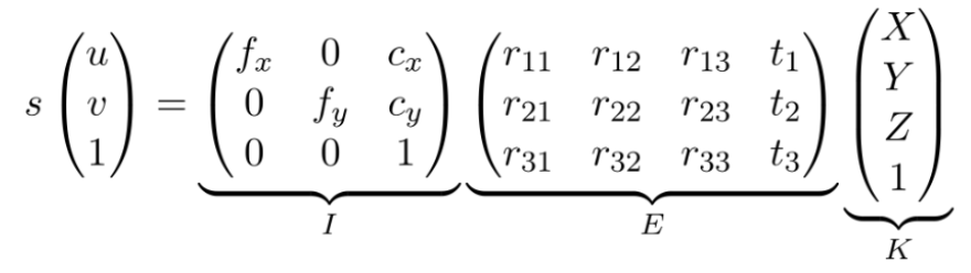
Figure 1. Formula to obtain 2D pixel coordinates from 3D world coordinates and the I and E matrices
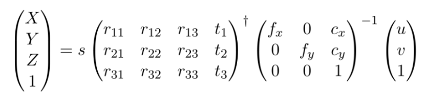
Figure 2. Formula to obtain 3D world coordinates from the 2D image coordinates and the I and E matrices.
However, the equations assume that the 2D point is in the image plane. Thus, the depth estimation in 3D space can be imprecise.
Stereo vision can be used to mitigate this problem. It combines two camera images to compute the intersection between the camera and the image point line to obtain the real depth in 3D space. Unfortunately, incorporating a second camera introduces additional complexities to the computation of 3D points. Challenges such as frame synchronization issues and inaccuracies in reprojection arise, degrading depth accuracy over distance and time

Figure 3. Stereo projection
A clever solution to avoid the use of stereo cameras and hence avoid their drawbacks is assuming that all points to be detected are coplanar, and by mapping the transformations of this plane, an exact 3D depth estimation can be achieved.
This plane estimation is usually performed with a homography matrix estimation (Figure 4). It focuses on points residing within a two-dimensional plane, reducing the problem's complexity significantly compared to mapping the entire three-dimensional space as the standard camera calibration does.
The homography matrix obtained from combining the camera's extrinsic and intrinsic parameters is the product of both matrices without the third column of the extrinsic matrix (Figure 5). Removing that third column can be done as the planar Z is 0, considering only points in the same plane XY, also known as coplanar points.
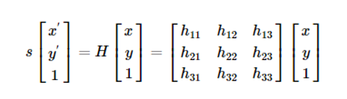
Figure 4. Homography matrix definition
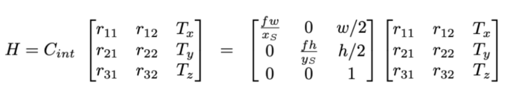
Figure 5. Homography matrix formula
Knowing both extrinsic and intrinsic parameters is impractical for real-world situations. Thus, other approaches such as Random Sample Consensus (RANSAC), Direct Linear Transform (DLT), or Least Square Estimation can be employed to compute and estimate the nine parameters of the 3x3 homography matrix, given a minimum of four corresponding points identified in both images.
To achieve precise calibration, it's crucial that these reference points are meticulously selected and accurately measured.
The simplest way to obtain these calibration points is to select them from the field manually. This task is relatively simple for static cameras, as the points must be chosen only once. Still, for the case of a video in which the camera has some movement, the calibration would need to be done at each frame to maintain reprojection consistency.
Scene calibration
Our first approach for obtaining the homography matrix uses the classical computer vision algorithm called RANSAC for the matrix computation and a graphic user interface (GUI) (Figure 1) to ease each image's selection points correspondence process.
In our case, we focused on obtaining the bird's view of a soccer scene image by mapping matching points from the soccer scene and a soccer field template, also called key points. When the user has inserted the matching points, the homography matrix is estimated. Once warped with the field template, the 3D real-world coordinates can be computed by scaling the 2D pixel coordinates with the real-world field dimensions.
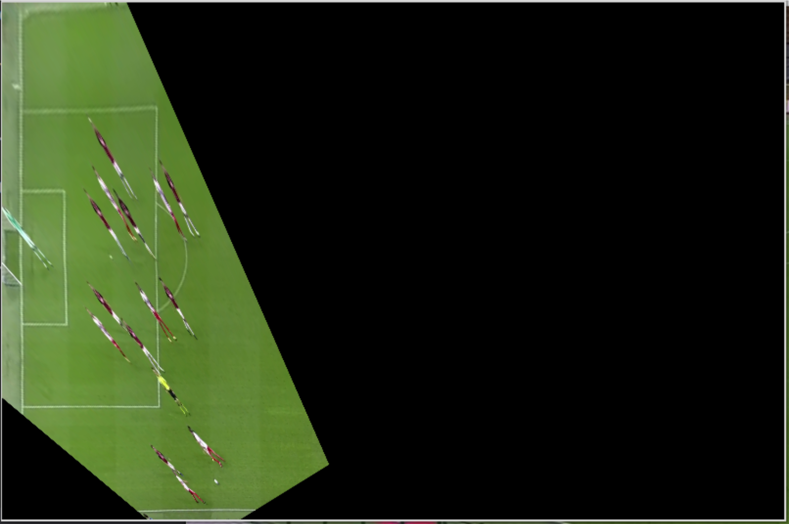
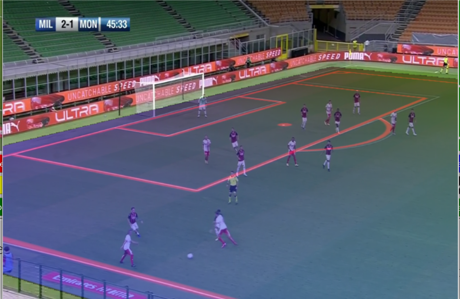
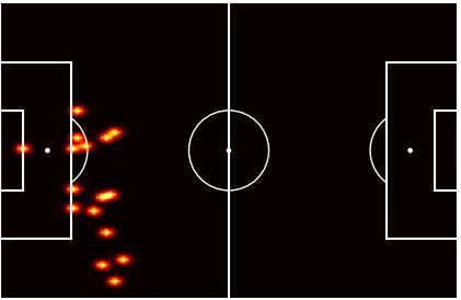
Not only is the Manual Tool able to obtain the homography matrix, but it also allows the position and computing of distances among players, from 2D pixel to 3D real-world coordinates. Moreover, it also outputs the warped image, its bird view projection, and a heatmap of the players.
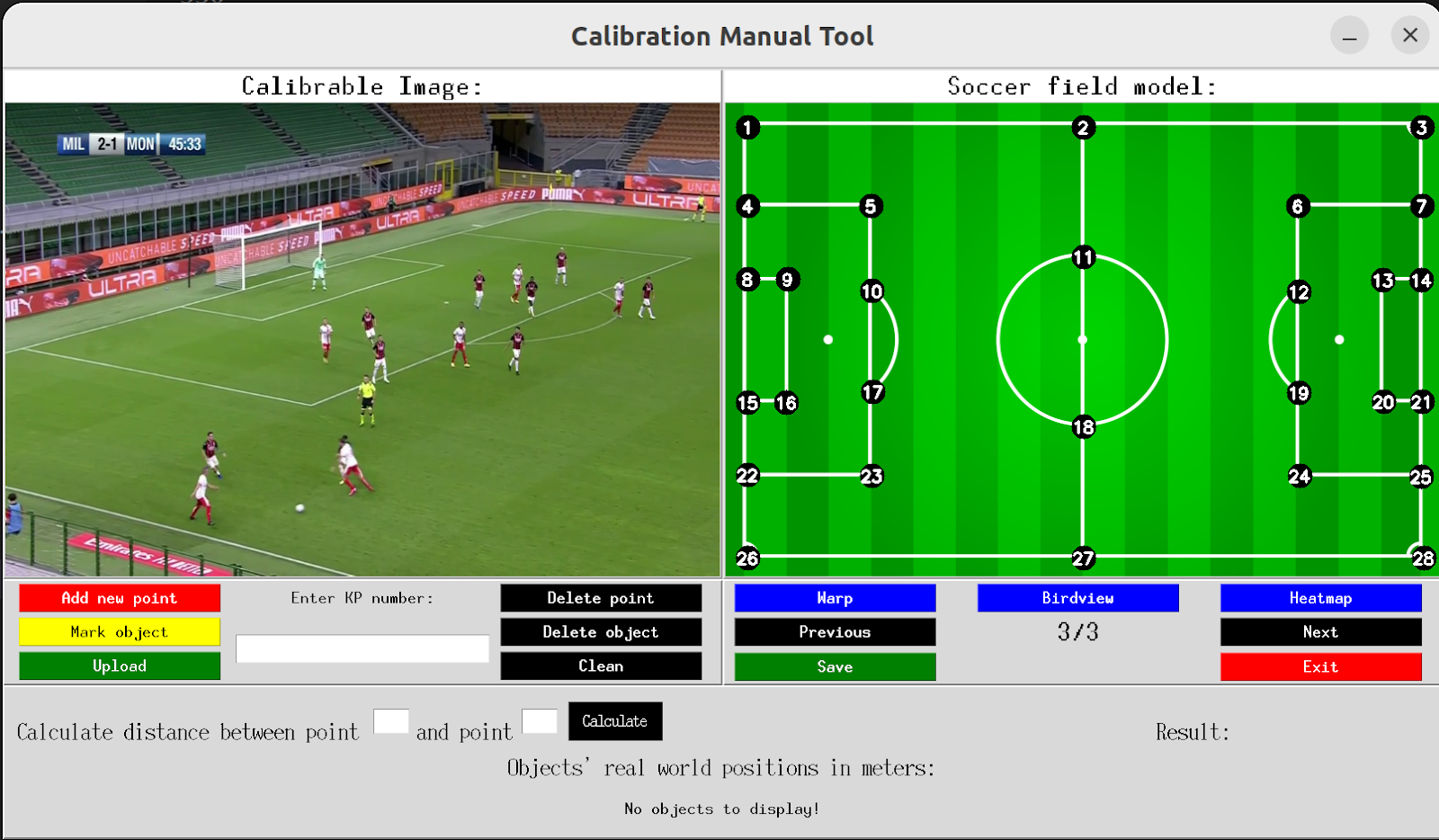
Figure 6. Manual Calibration Tool GUI
This tool requires Soccer field dimensions for distance reference, as not all the fields have the exact dimensions (Figure 7). Matching key points between the reference map and the real image, to ease the identification and increase the accuracy, have been reduced to 28 key points corresponding to the field lines' intersection points (Figure 8).
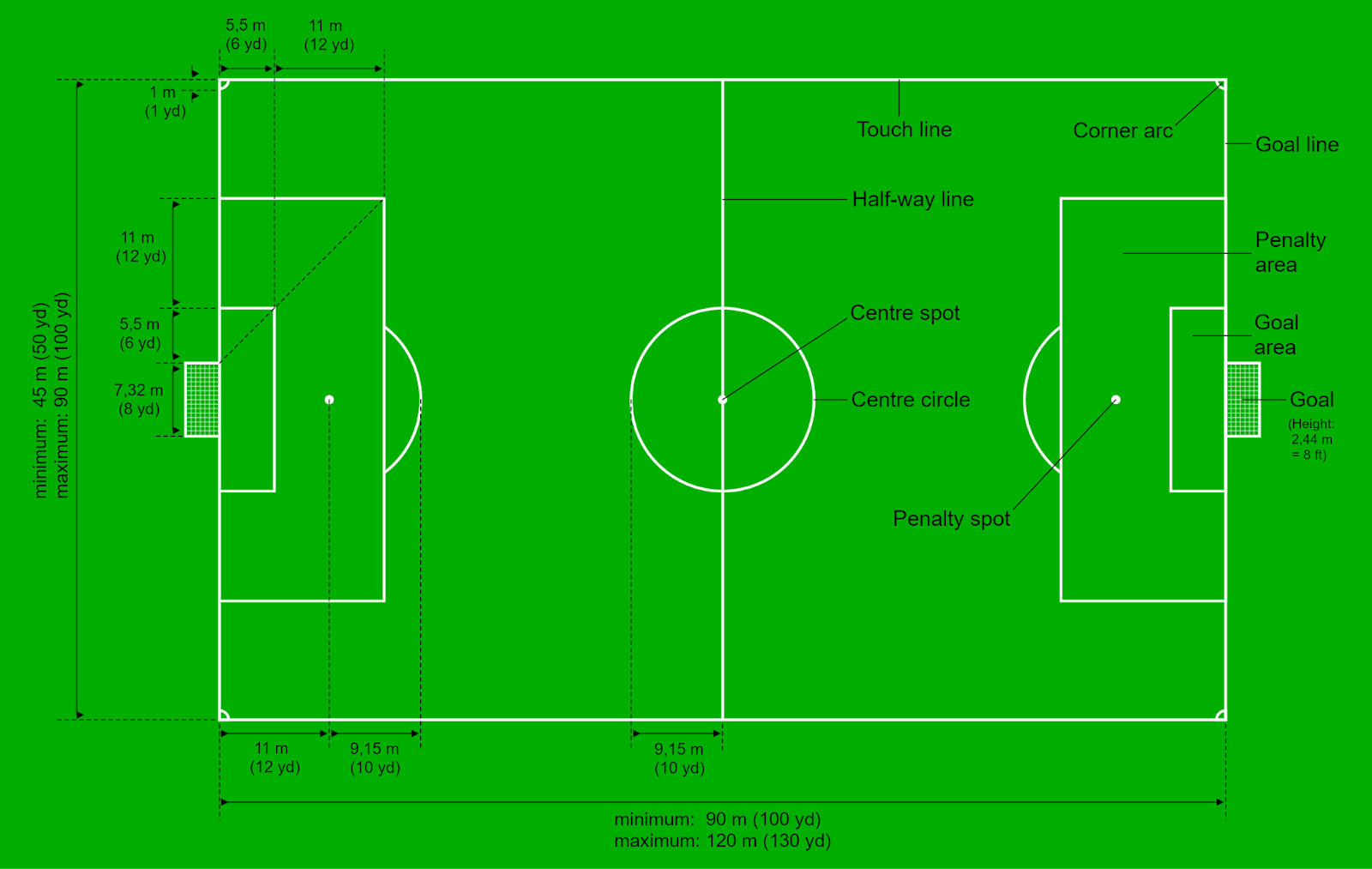
Figure 7. Soccer Field Dimensions Rules
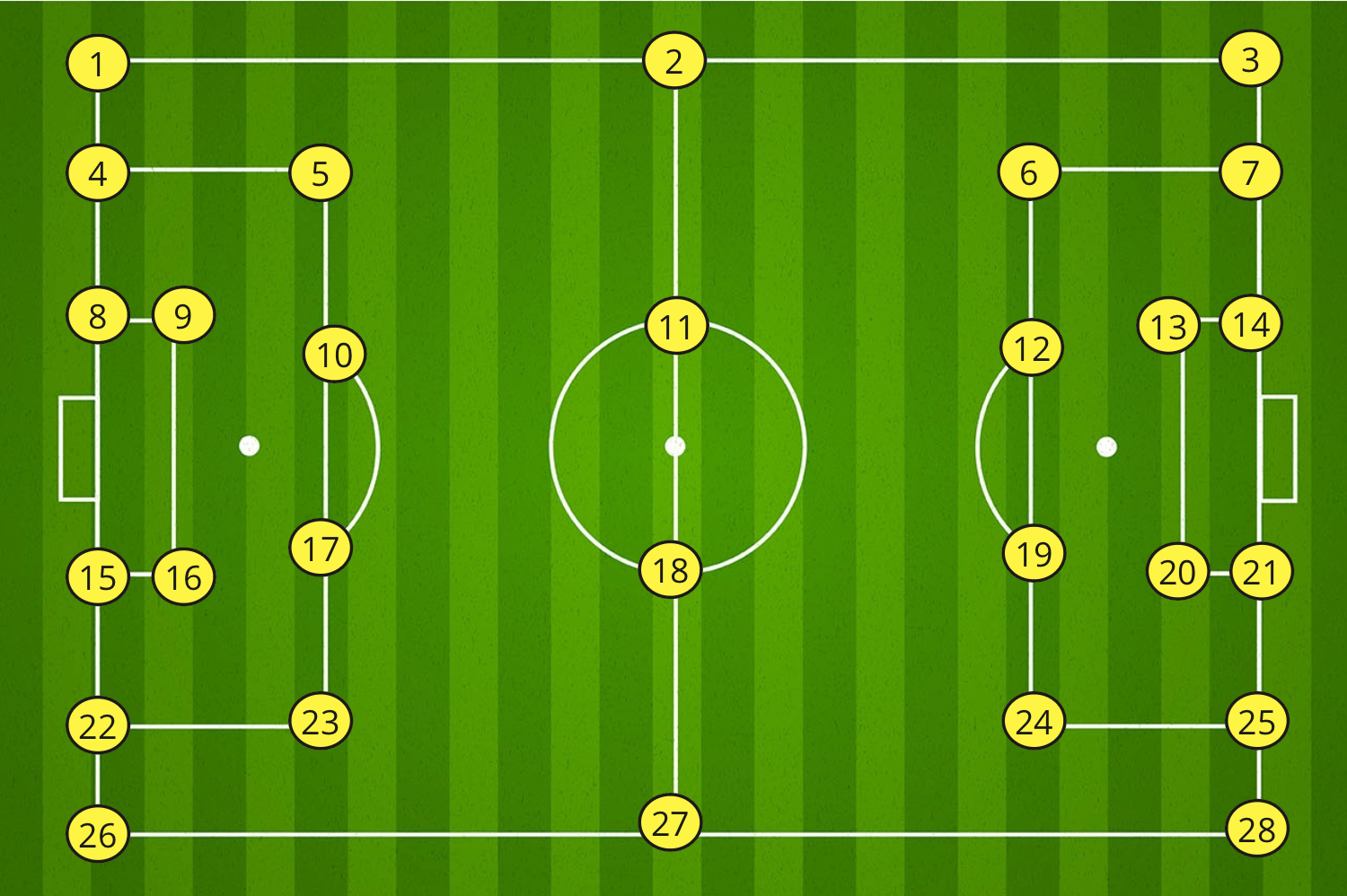
Figure 8. Soccer Field Key Points Guide
The user will select a point from the right map, and then they will select the same point in the image from the left (Figure 9). Once four points are at least selected, the system can estimate the homogeneous matrix.
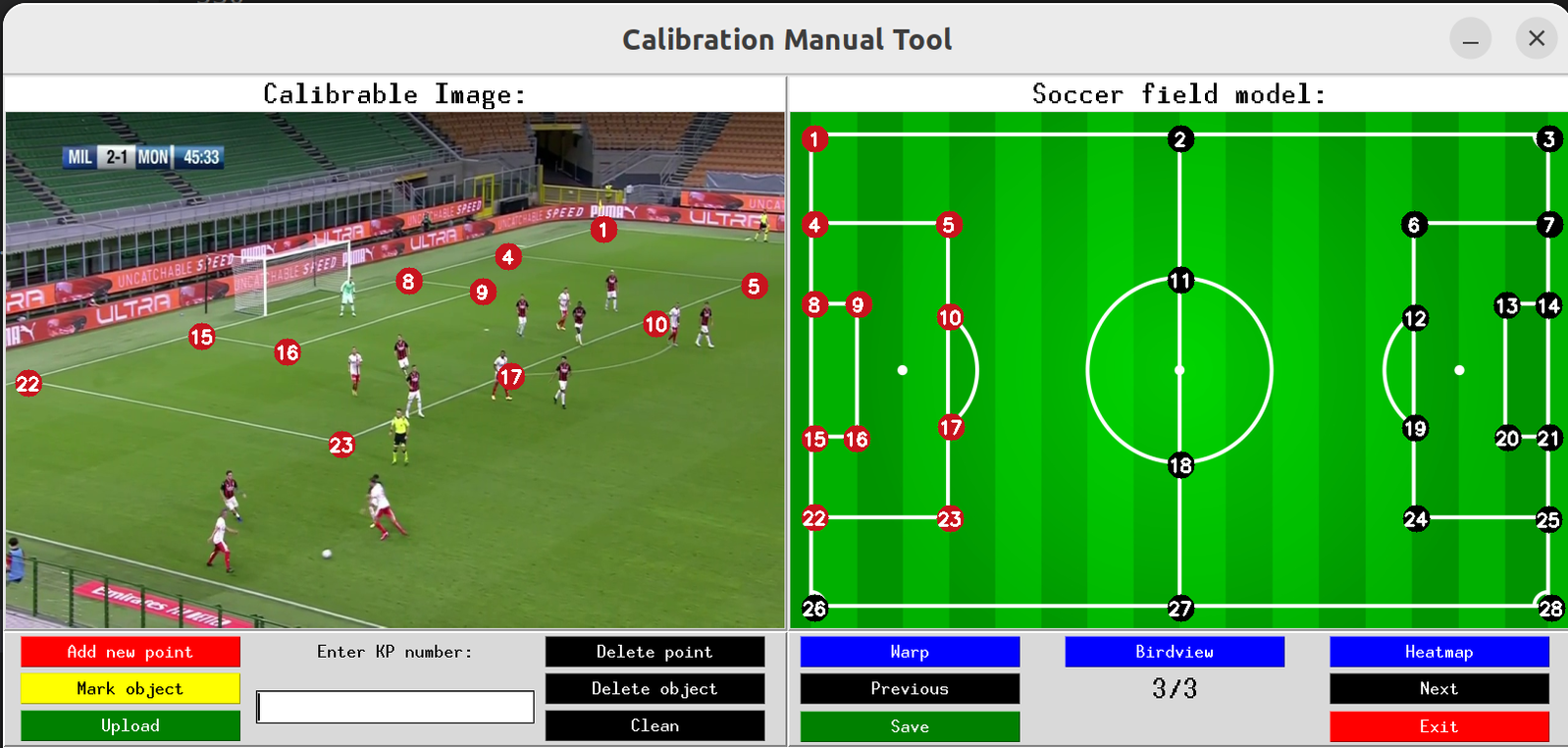
Figure 9. Key points selection example (selected -> red)
With the homography matrix computed, to obtain the real-world coordinates of an object, it only needs to click on the object of interest in the real image. Then, a yellow circle marker should appear on both pictures as it positions the player's position (Figure 10).
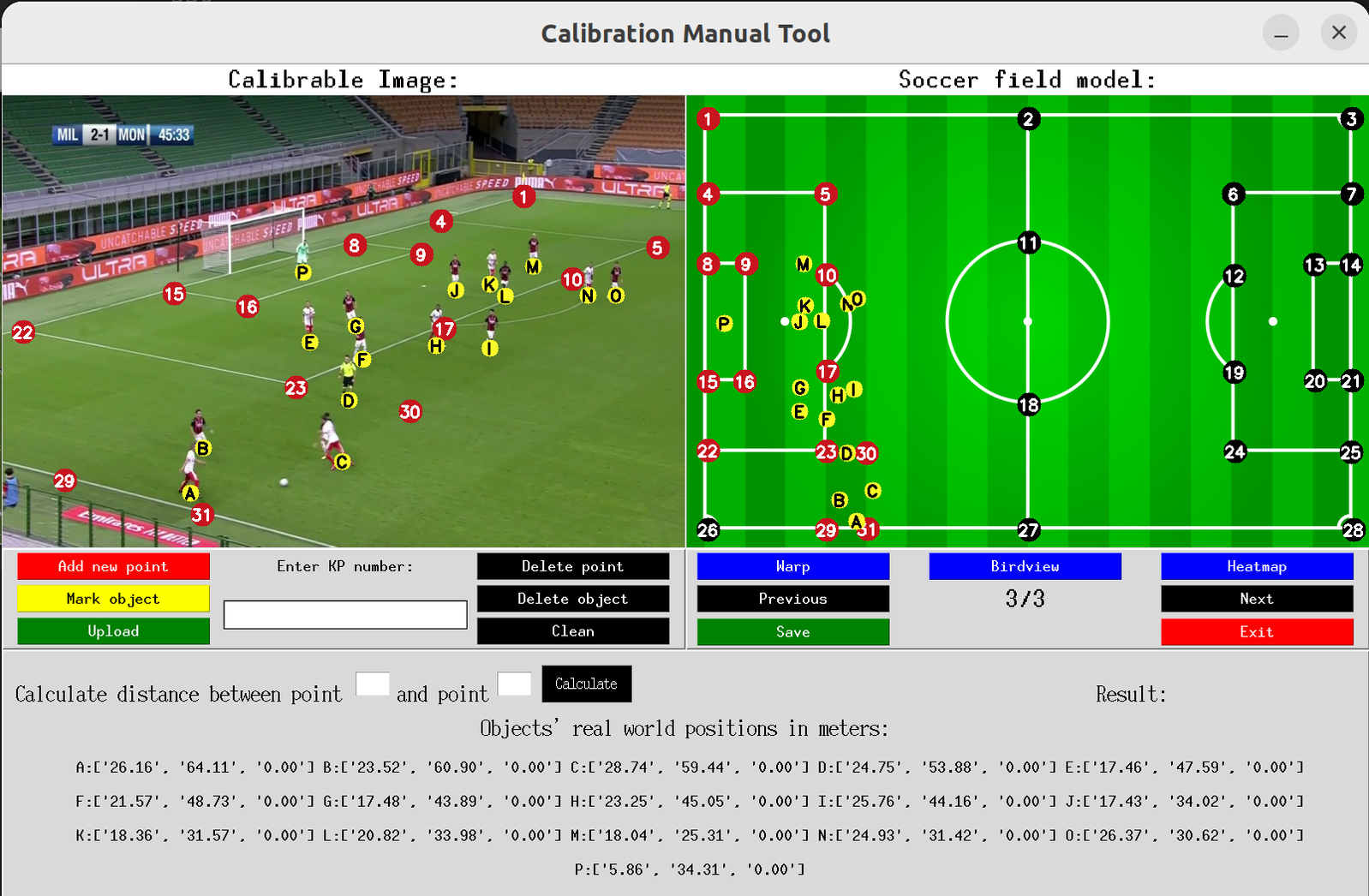
Figure 10. Objects selection and real-world positions displayed
Finally, the output of the warped image, the bird view, and the player's heatmap, if any player is selected, can be obtained.
|
|
|
|
Conclusions
Despite achieving outstanding results with the scene Calibration Manual Tool, it is inefficient as it requires much human interaction for each step. Additionally, the key point positioning relies on human precision, which can lead to suboptimal performance when the accuracy is not good enough.
Consequently, it becomes evident that integrating an automated approach is essential for enhancing the system's efficiency. Fortunately, several computer vision algorithms can perform keypoint detection swiftly and with greater precision. Future posts will explore these algorithms, exploring their capabilities and applications in detail.
Don't miss the opportunity to take your computer vision applications to the next level. Contact us now!

